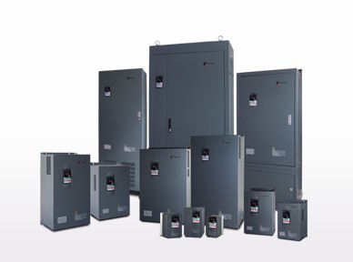
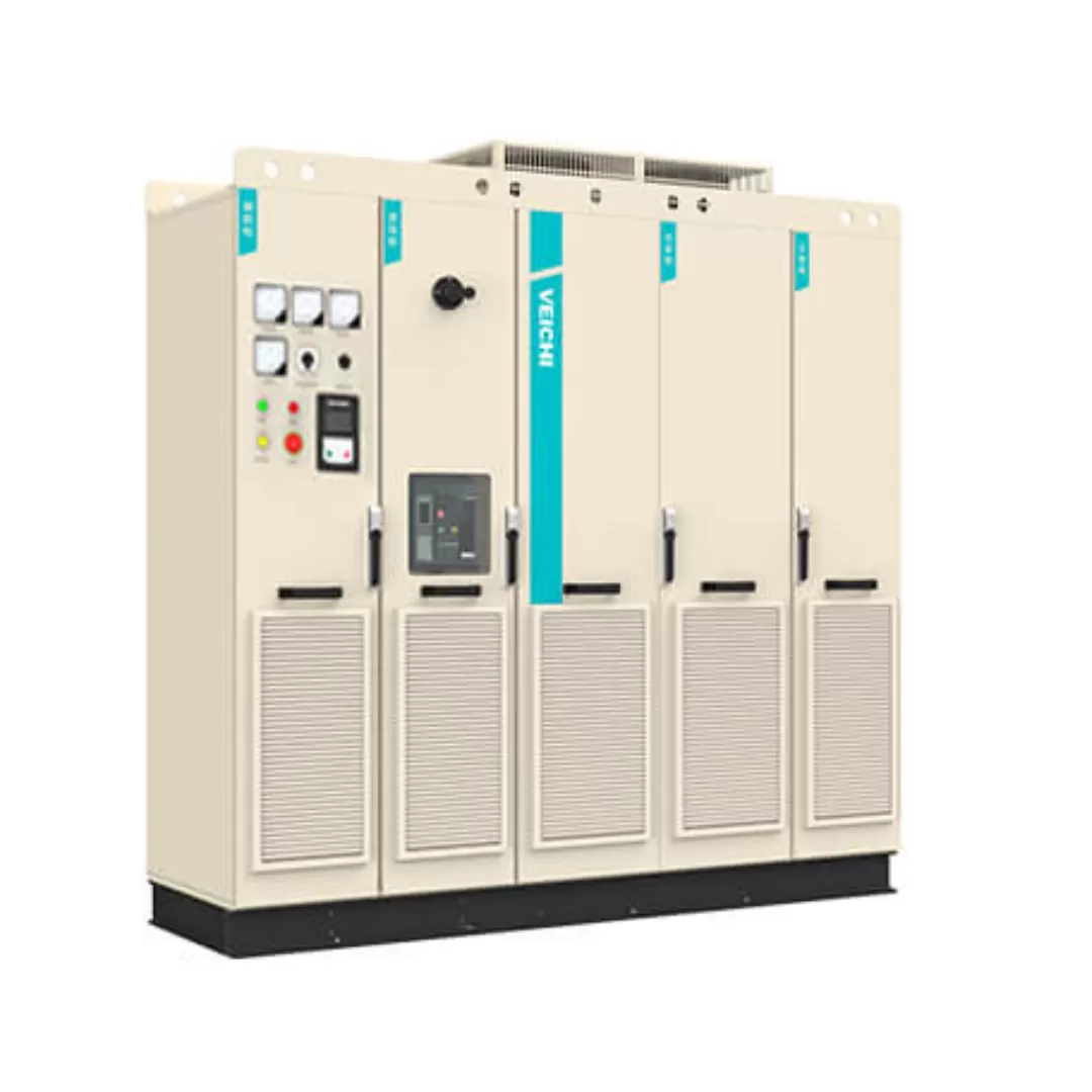
ตู้อินเวอร์เตอร์ AC800 — อินเวอร์เตอร์อุตสาหกรรมประสิทธิภาพสูงสำหรับงานหนัก
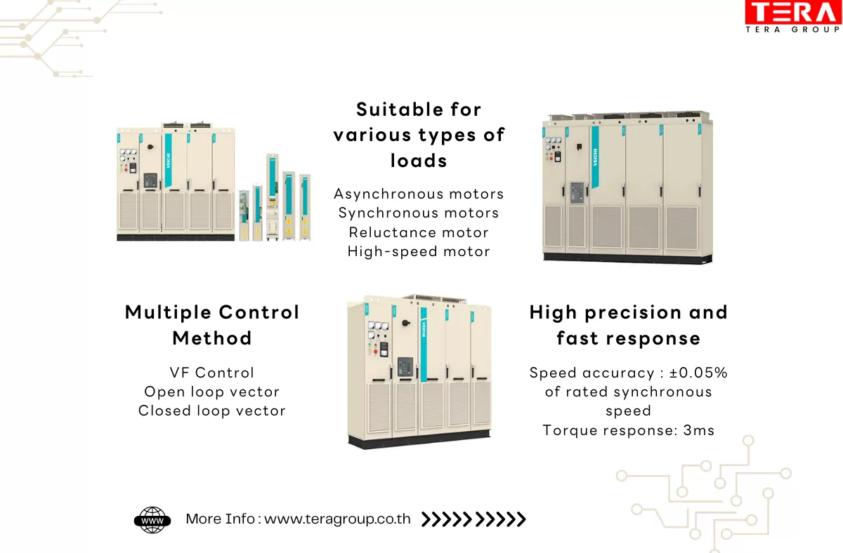
ตู้อินเวอร์เตอร์ AC800 เป็นอินเวอร์เตอร์แบบ Multi-drive ที่ออกแบบมาเพื่อรองรับงานอุตสาหกรรมหลากหลายประเภท มอบการควบคุมมอเตอร์ที่แม่นยำ ประหยัดพลังงาน และมีโครงสร้างที่แข็งแรงทนทาน เหมาะกับไลน์ผลิตที่ต้องการความเสถียรสูง ใช้งานได้ดีในสภาพแวดล้อมที่มีความต้องการสมรรถนะหนักต่อเนื่อง และตอบโจทย์ธุรกิจที่กำลังมองหาตู้อินเวอร์เตอร์คุณภาพสูงที่ทั้งคงทนและให้ผลลัพธ์สม่ำเสมอ
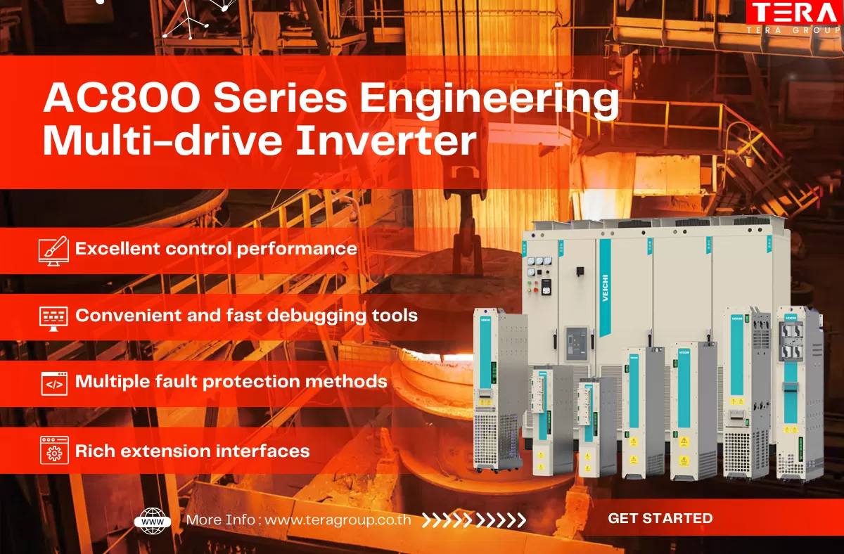
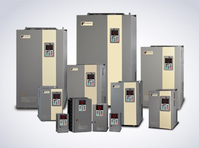
คุณสมบัติเด่นของตู้อินเวอร์เตอร์ AC800 Series (Engineering Multi-drive Inverter)
- ประสิทธิภาพการควบคุมยอดเยี่ยม ควบคุมมอเตอร์ได้แม่นยำ เสถียร รองรับงานอุตสาหกรรมที่ต้องการความละเอียดสูง
- เครื่องมือ Debugging เร็วและใช้งานง่าย ช่วยลดเวลาเซตอัป ลดความผิดพลาด เพิ่มประสิทธิภาพงานติดตั้ง
- ดีไซน์แบบโมดูลาร์ + ระบบ Common DC Bus ขยายระบบง่าย ลดต้นทุนการเดินสาย เหมาะกับไลน์ผลิตที่ต้องการประหยัดพลังงาน
- รองรับพอร์ตเชื่อมต่อครบครัน เชื่อมต่อกับระบบอัตโนมัติและอุปกรณ์โรงงานได้หลากหลาย ตอบโจทย์ทุกอุตสาหกรรม
- ระบบป้องกันความผิดปกติหลายรูปแบบ ยกระดับความปลอดภัย ทำงานเสถียร ลด Downtime ของโรงงาน
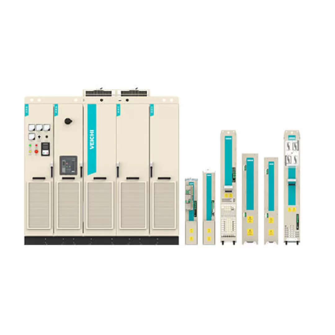
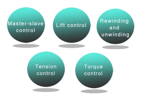
มีโมดูลฟังก์ชันในตัวหลายรูปแบบ
รองรับการใช้งานหลากหลาย เพิ่มความยืดหยุ่นให้ตู้อินเวอร์เตอร์ AC800 ปรับใช้ได้กับทุกงานอุตสาหกรรม ทั้งระบบควบคุมมอเตอร์และงานอัตโนมัติที่ต้องการความแม่นยำสูง
Built-in multiple function modules
เครื่องมือ Debugging ที่รองรับทุกสภาพการทำงาน
- VCSoft ซอฟต์แวร์ดีบักระดับอุตสาหกรรม ออกแบบมาเพื่อเพิ่มความสะดวกในการตั้งค่าตู้อินเวอร์เตอร์ AC800
- หน้าจอใช้งานแบบกราฟิก (GUI) เมนูชัดเจน ใช้งานง่าย แม้เป็นระบบควบคุมที่ซับซ้อน
- ตั้งค่าระบบได้รวดเร็ว ทั้งการตั้งค่าพารามิเตอร์ ตรวจจับความผิดปกติ และดูแลบำรุงรักษาระบบ
- ลดเวลาเซตอัป & เพิ่มเสถียรภาพการทำงาน ช่วยให้งาน Commissioning และการบริการหลังการติดตั้งรวดเร็วขึ้นอย่างเห็นได้ชัด
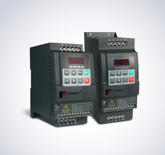
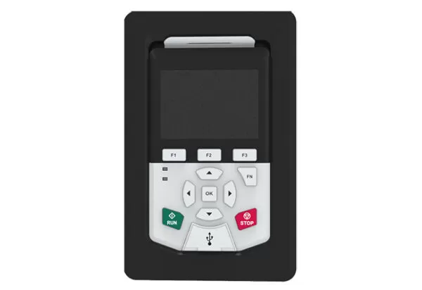
คีย์บอร์ดควบคุมแบบ Multi-function ของตู้อินเวอร์เตอร์ AC800
- หน้าจอแสดงผลแบบ LCD มองเห็นค่าสถานะและพารามิเตอร์ได้ชัดเจน
- รองรับ 2 ภาษา (จีน–อังกฤษ) ใช้งานง่ายในงานอุตสาหกรรมสากล
- ดีบักผ่าน Bluetooth ในตัว เชื่อมต่อมือถือหรืออุปกรณ์พกพาเพื่อปรับแต่งค่าได้สะดวก ไม่ต้องใช้สาย
- คัดลอกและกู้คืนพารามิเตอร์ได้ทันที ลดเวลาตั้งค่าเครื่องใหม่ เหมาะกับการใช้งานในหลายไลน์ผลิต
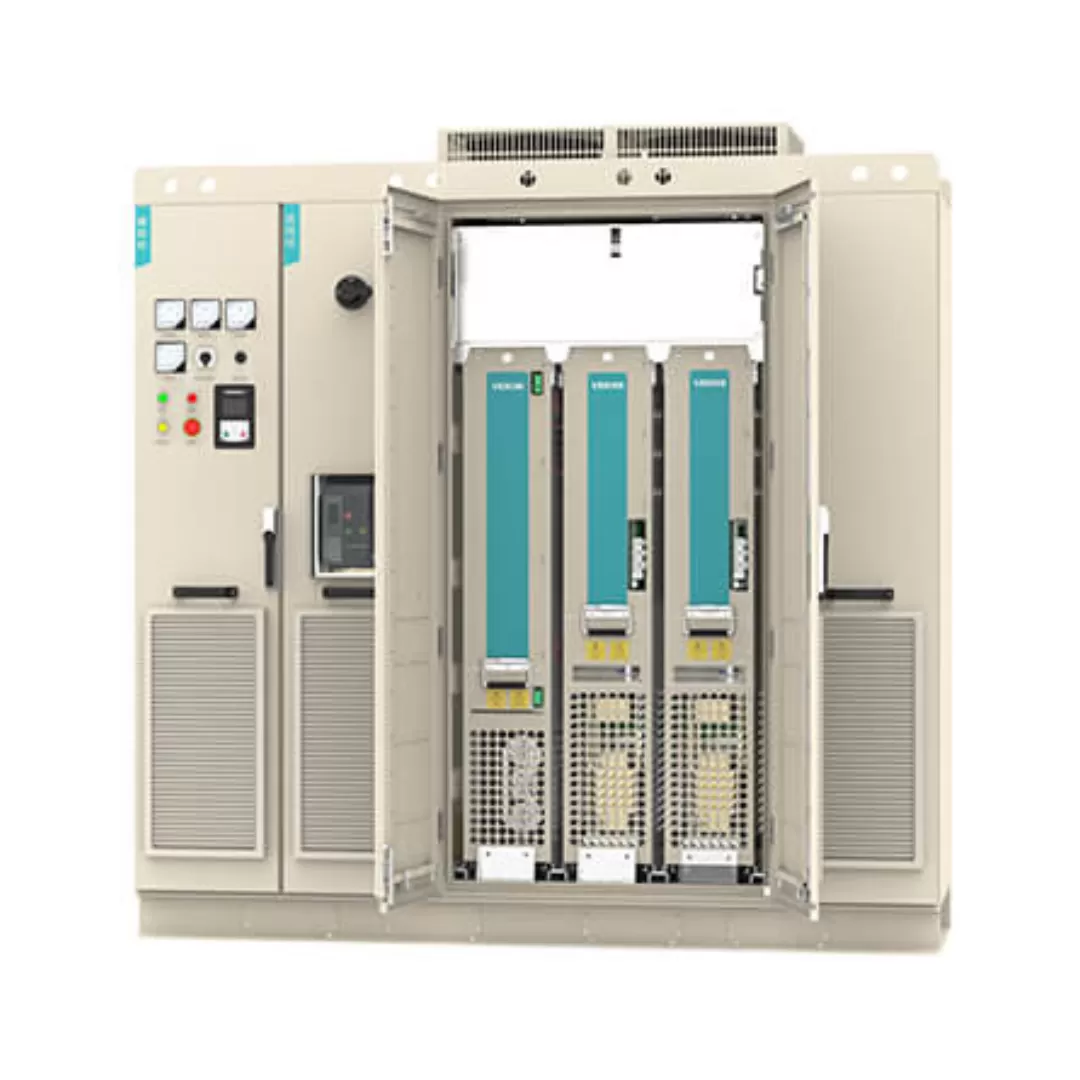
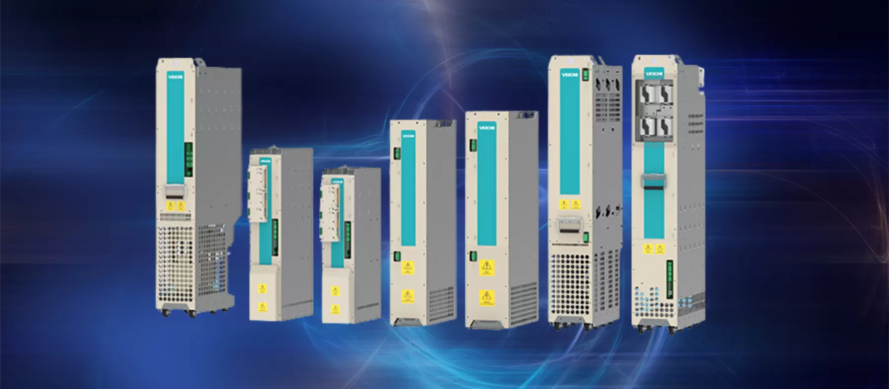
ไซน์แบบโมดูลาร์ (Modular Design) ของตู้อินเวอร์เตอร์ AC800
- โมดูลแยกอิสระครบชุด ไม่ว่าจะเป็นฟิลเตอร์, เรคติไฟเออร์, อินเวอร์เตอร์ และเบรก ต่างถูกออกแบบให้เป็นโมดูลมาตรฐานแยกกัน ช่วยให้บำรุงรักษาง่ายและลด Downtime
- ดีไซน์แบบ Book-type ช่วยจัดวางในตู้คอนโทรลได้สะดวก ประหยัดพื้นที่ และลดขนาดตู้โดยรวม เหมาะกับโรงงานที่ต้องการเพิ่มประสิทธิภาพพื้นที่ใช้สอย
- จัดสรรโมดูลได้ยืดหยุ่นตามโหลดมอเตอร์ ปรับกำลังให้เหมาะสมกับกำลังงานที่ใช้งานจริง ช่วยประหยัดพลังงาน และเพิ่มเสถียรภาพของระบบควบคุม
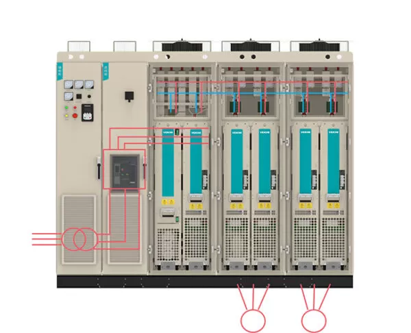
ระบบ Common DC Bus ในตู้อินเวอร์เตอร์ AC800
- ประหยัดพลังงาน 5%–30%
เหมาะกับงานโหลดแบบยกลง, Winding/Unwinding หรือโหลดที่เกิดพลังงานย้อนกลับ โดยพลังงานที่สร้างขึ้นจะถูกแลกเปลี่ยนระหว่างโมดูลผ่าน DC Bus ช่วยลดการใช้พลังงานรวมของระบบ - ลดภาระของเรคติไฟเออร์และโมดูลเบรก
การกระจายพลังงานผ่าน DC Bus ช่วยลดกระแสที่ต้องรับโดยตรง ทำให้ระบบมีความเสถียรสูงขึ้นและลดการสึกหรอของอุปกรณ์ - ใช้แหล่งจ่ายร่วมจาก Rectifier Unit เดียว
ลดจำนวนอุปกรณ์ Switching และ Braking ในวงจรหลัก ทำให้ระบบเรียบง่ายขึ้นและลดต้นทุนโดยรวม - ลดปริมาณและความยุ่งยากของการเดินสาย
ระบบควบคุมมีความซับซ้อนน้อยลง ช่วยลดค่าอุปกรณ์ ค่าแรงติดตั้ง และเพิ่มความคุ้มค่าให้ผู้ใช้งาน
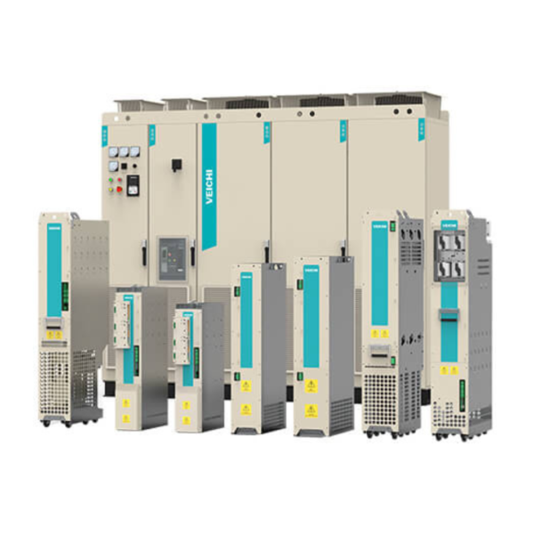
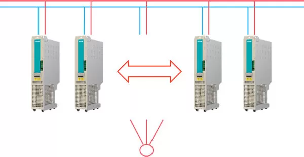
รองรับการต่อโมดูลแบบขนาน (Parallel) เพิ่มกำลังได้สูงสุดถึง 5600kW
- รองรับการต่อร่วมหลายโมดูล (Multi-module Parallel)
เพิ่มกำลังระบบได้ยืดหยุ่นตามความต้องการใช้งานของโรงงาน ช่วยให้ตู้อินเวอร์เตอร์ AC800 รองรับงานหนักระดับอุตสาหกรรมได้แบบไร้ข้อจำกัด - Busbar ใช้กระแสตรงร่วมกัน (Shared DC Bus)
ใช้ชุด V8 Units สำหรับการทำงานแบบขนาน ช่วยกระจายโหลดอย่างมีประสิทธิภาพและเพิ่มความเสถียรของระบบ - รองรับกำลังสูงสุด 2800 kW (ระบบ 400V)
เหมาะกับงานควบคุมมอเตอร์กำลังสูงในโรงงานผลิตทั่วไป - รองรับกำลังสูงสุด 5600kW (ระบบ 690V)
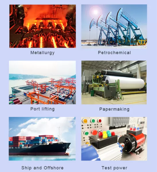
ตอบโจทย์งานอุตสาหกรรมหนัก เช่น เหล็ก–เหมือง–กระดาษ–ปิโตรเคมี ที่ต้องการอินเวอร์เตอร์กำลังสูงพิเศษ
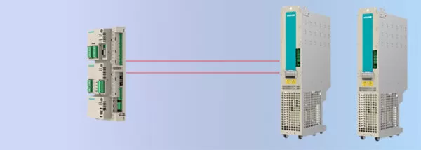
ระบบควบคุมหลัก VCU (Main Controller) ครอบคลุมทุกโมดูล
- ควบคุมครบทุกส่วนของระบบ (Full Coverage VCU)
หน่วยควบคุมกลาง VCU เชื่อมโยงการทำงานของทุกโมดูลในตู้อินเวอร์เตอร์ AC800 เพื่อให้ระบบทำงานแม่นยำและเสถียรสูงสุด - เชื่อมต่อข้อมูลระหว่าง VCU กับทุกโมดูล
ส่งผ่านข้อมูลแบบเรียลไทม์ ทำให้การควบคุมโหลด การปรับพารามิเตอร์ และการตรวจสอบสถานะมีความถูกต้องมากขึ้น - สื่อสารผ่านใยแก้วนำแสง (Optical Fiber)
ป้องกันสัญญาณรบกวนได้ดีเยี่ยม เหมาะกับสภาพแวดล้อมโรงงานที่มีสัญญาณรบกวนไฟฟ้าสูง ช่วยให้ระบบควบคุมทำงานเสถียรต่อเนื่อง
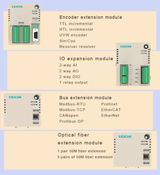
รองรับโมดูลเสริมหลากหลาย (Expansion Modules)
- รองรับการติดตั้งโมดูลเสริมหลายประเภท
เพิ่มฟังก์ชันการทำงานของตู้อินเวอร์เตอร์ AC800 ให้เหมาะกับงานอุตสาหกรรมแต่ละรูปแบบ ทั้งระบบสื่อสาร การควบคุม และการป้องกัน - ปรับการใช้งาน Bus ให้เหมาะกับความต้องการ
สามารถเลือกการตั้งค่าและการเชื่อมต่อ Bus ได้ตามโหลดและเงื่อนไขการใช้งาน ช่วยให้ระบบมีความยืดหยุ่นและปรับแต่งได้สูง
ระบบป้องกันครบวงจรของตู้อินเวอร์เตอร์ AC800 — ปลอดภัย เสถียร ใช้งานมั่นใจ
1) Inverter Protection – ป้องกันความผิดปกติของอินเวอร์เตอร์
- ป้องกันลัดวงจร (Short Circuit)
- ป้องกันกระแสเกิน (Overcurrent)
- ป้องกันแรงดันเกิน–แรงดันตก (Over/Undervoltage)
- ตรวจจับไฟเฟสหาย (Phase Loss)
- ป้องกันความร้อนสูงเกิน (Overheating)
- ป้องกันโหลดเกิน (Overload)
- ตรวจจับ Encoder หลุดสัญญาณ
- มีระบบป้องกันทั้งหมดกว่า 30 รูปแบบ พร้อมแบ่งระดับความรุนแรงหลายชั้น
2) Functional Safety – ระบบความปลอดภัยเชิงฟังก์ชัน
- มาตรฐาน STO – Safe Torque Off
- มี Hardware Detection ตัดกำลังมอเตอร์โดยบล็อก Drive Pulse
- ป้องกันการสตาร์ทมอเตอร์โดยไม่ตั้งใจ เพิ่มความปลอดภัยต่อบุคลากรและอุปกรณ์
3) Motor Protection – ป้องกันมอเตอร์
- รองรับการตรวจวัดอุณหภูมิ PT100 เพื่อป้องกันความร้อนสูงเกิน
- ช่วยยืดอายุการใช้งานมอเตอร์และลดโอกาสเกิดความเสียหาย
4) Black Box – ระบบบันทึกเหตุขัดข้อง
- มี SD Card ในตัว
- เก็บข้อมูลรูปคลื่น (Waveform) ก่อนและหลังเหตุขัดข้อง ช่วยวิเคราะห์ต้นเหตุได้แม่นยำ
5) Fuse Protection – ป้องกันเมื่อโมดูลเกิดความเสียหาย
- หากมีโมดูลใดผิดปกติ ฟิวส์จะทำงานอย่างรวดเร็วเพื่อป้องกันความเสียหายลุกลาม
6) Module Exit Mechanism – หน่วยเสียสามารถถอดจากระบบแบบออนไลน์
- โมดูลที่เสียสามารถแยกออกได้ทันทีโดยไม่ต้องหยุดระบบทั้งหมด
- ระบบจะยังคงทำงานต่อแบบ Derating เพื่อไม่ให้ไลน์ผลิตหยุดชะงัก
7) Quick Change – คืนระบบกลับมาทำงานได้เร็ว
- ไม่ต้องเปลี่ยนหน่วยควบคุม VCU
- ไม่ต้องตั้งค่าพารามิเตอร์ใหม่
- ระบบสามารถกลับมาทำงานได้ภายใน 30 นาที หลังเปลี่ยนโมดูลเสีย
ระบบป้องกันหลายชั้น ปลอดภัยและเสถียรสูง
ตู้อินเวอร์เตอร์ AC800 มาพร้อมระบบจัดการความผิดปกติและการป้องกันหลากหลายรูปแบบ ตั้งแต่การป้องกันลัดวงจร กระแสเกิน แรงดันผิดปกติ ความร้อนสูงเกิน ไปจนถึงระบบความปลอดภัยมาตรฐาน STO เพื่อป้องกันการทำงานโดยไม่ตั้งใจ ทำให้ทั้งระบบมีความปลอดภัย เสถียร และลดความเสี่ยงต่อความเสียหายของอุปกรณ์และมอเตอร์ เหมาะกับโรงงานที่ต้องการความมั่นใจสูงในทุกกระบวนการผลิต